
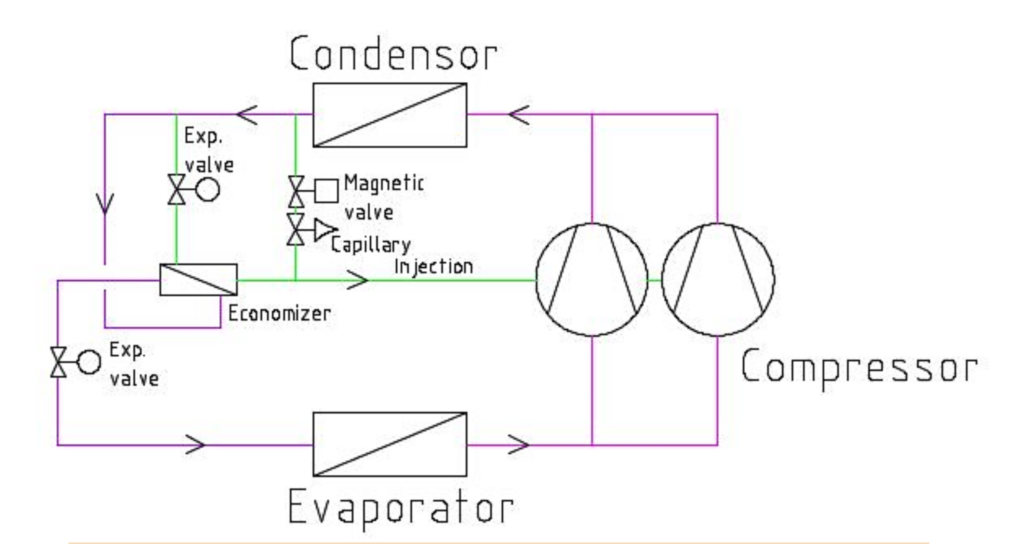
Figure 1. Principal refrigerant circuit with V.L.l.P. Vapor & Liquid Injection Power.

Figure 2. Change in heat factor as a function of flow temperature.

Figure 3. Change in heat output as a function of flow temperature.
Qvantum QLC Control system
Qvantum LB4 is equipped with the QLC control system as standard. QLC stands for Qvantum Logic Controller. The unit is controlled and operated via the principal of liquid condensation or solid/half solid condensation. All control parameters, such as outdoor temperature compensated set-point curve for supply, hot water temperature, and auxiliary heat, are set via the self-instructing control system. Required protection and safety features are built into the QLC control system.
The system is managed via a 5,7″ panel mounted in the heat pump. All parameters can be set via the panel. The panel displays a dynamic flow chart panel with all temperatures and operating modes measured and controlled. The QLC control system also logs temperatures and events, which facilitates setup and analysis.
The system communicates via Modbus. Modbus TCP is standard. The system also has a webserver which allows the QLC control system to communicate with a web browser on a PC or cell phone.
As an option, the unit can be equipped with a display that allows for dynamic flow images and extended network functionality.
The temperature to the heating system is controlled according to the selected outdoor temperature compensated curve. Hot water preparation, if such a function is required, takes place via a switching valve.
In bivalent systems, the control system switches on additional heat when necessary and after a time delay. The auxiliary heat can be selected to “take over” the hot water preparation as the first step and thereby release power from the heat pump to the heating system.
The QLC control system can control up to 8 heat pumps in sequence with automatic operating time equalization between the different heat pumps. The QLC control system is configured at commissioning depending on the selected system solution and type and number of heat pumps.
The heat pump can be configured for control via an overlaying external control system if required. Set points can be changed via Modbus so that the controller’s regulators are set by the master controller. It is also possible to configure the system so that the heat pump is fully controlled by the overlaying external control system. In this case, the QLC control system is used only for alarm and protection functions.
E.g., Temperatures readable via Modbus *)
1: Heat pump heat carrier — in
2: Heat pump heat carrier — out
3: Heat pump hot gas temperature
4: Heat pump brine — in
5: Heat pump brine — out
6: Radiator circuit supply
7: Outdoor temperature
*) See Modbus description for complete information
All relay outputs are also readable. You can thus transfer the operating status of compressors, pumps, fans, etc. which are controlled via the heat pump.
Set points for hot water temperature and control curve for radiator circuit can be read and adjusted. From the expansion valve control unit, the current evaporating temperature, pressure, overheating, the degree of opening of the expansion valve can be monitored via Modbus.

DEFROSTING
The LB4 uses an effective defrosting system which makes it possible to make use of the heat pump even when the temperature is low. It is only active when needed, when the moist in the air freezes on the aircoil fins.
The fin thickness is 0,25 mm and the fin pitch is 5 mm. The 5 mm fin pitch will allow long intervals between defrosting.
Placement
The outdoor air unit is placed where it is most appropriate. The standard design of the brine system is dimensioned for a total length of 2 x 25 meters between the indoor heat pump unit and the outdoor air coil. If longer distances are desired, the capacity of the brine pump can be increased.
Electronic Expansion Valve
Qvantum LB4 heat pumps are equipped with two electronic expansion valves. A valve for the evaporator circuit and a valve for the economizer circuit.
The expansion valves have their own electronic control unit with display that shows evaporation pressure, temperature, overheating etc. for the two circuits. Via Modbus, these variables can be transferred to an overlaying control system.
Refrigerant
All Qvantum LB4 heat pumps uses R-407C refrigerant.
Brine Circuit
Qvantum LB4 has pipes filled with a mixture of water and antifreeze between the outdoor air battery and the compressor unit/defrosting tank. In most cases, water + ethylene glycol (45%) is used, but a mixture of water and methanol can also be used. Ethanol and propylene glycol cannot be used as anti-freeze agents.
PIPE Connections
Q48LB4 has top connections, see drawing Q-LB4- 48-001.
Q65 – 96LB4 have top connections, see drawing Q-LB4-65-96-001. Q123 – 192LB4 have top connections, see drawings Q-LB4-123-144-001 and Q-LB4-162-192-001.
Constructions
The unit is built on a robust stand of galvanized square tubes and covered with an effective sound- absorbing casing, consisting of powder-coated plates with sound-absorbing material inside. The top plate is made of patterned aluminum. The top and bottom are also covered with sound-absorbing material. The stand rests on adjustable rubber feet.
Access
The unit is constructed so that all components inside the heat pump are easily available by removing the cover plates, both for maintenance and replacement.
Options
The following options are available:
- Larger model of brine pump due to increased distance between heat pump unit and air coil. – Connecting QLC to network.
- The evaporator is a stainless steel, brazed heat exchanger, insulated with Armaflex insulation. – The condenser is a stainless steel, brazed heat
exchanger. - Electrical cabinet mounted on the left side of the unit, seen from the front (applies to Q65 – 192LB4).
- Equipment
Equipment
Compressor
All LB4 units are equipped with fully hermetic scroll compressors, 3-phase 400V.
Q48LB4 is equipped with 1 compressor. Q65-96LB4 are equipped with 2 compressors. Q123LB4 and Q144LB4 are equipped with 3 compressors.
Q162LB4 and Q192LB4 are equipped with 4 compressors.
Refrigerant circuit
Q48-144LB4 are equipped with 1 refrigerant circuit.
Q162LB4 and Q192LB4 are equipped with 2 refrigerant circuits.
Heat exchanger
Economizer is a brazed plate heat exchanger in stainless steel.
Hot gas heat exchanger (option) is a brazed plate heat exchanger in stainless steel.
Defrosting heat exchanger is a stainless steel, brazed heat exchanger.
Circulation pumps
Condensor- and evaporator pumps, external mounting
Defrosting pump, internal mounting
Control valve
Control valve for defrosting, internal mounting.
Refrigerant circuit
- Drying filter
- Sight glass with moisture indicator
- Solenoid valve with equipment for liquid
injection power (L.I.P.) - Electronic expansion valves for refrigerant
circuit and economizer (V.I.P.) - Pressure/temperature sensor
- Control equipment with display (Modbus) for
the main circuit - Pressure transmitter
- High- and low-pressure switch, manual reset – Service valves for refrigerant pressure
measurement - Rotalock valves
- Pressure protection equipment, high and low pressure
Testing
The units are test run and calibrated under design conditions using ClimaCheck.


